
P.B. Schoettle
300
the ball was determined. When realizing that
all points were situated in the same area, the
following reference lines were determined as
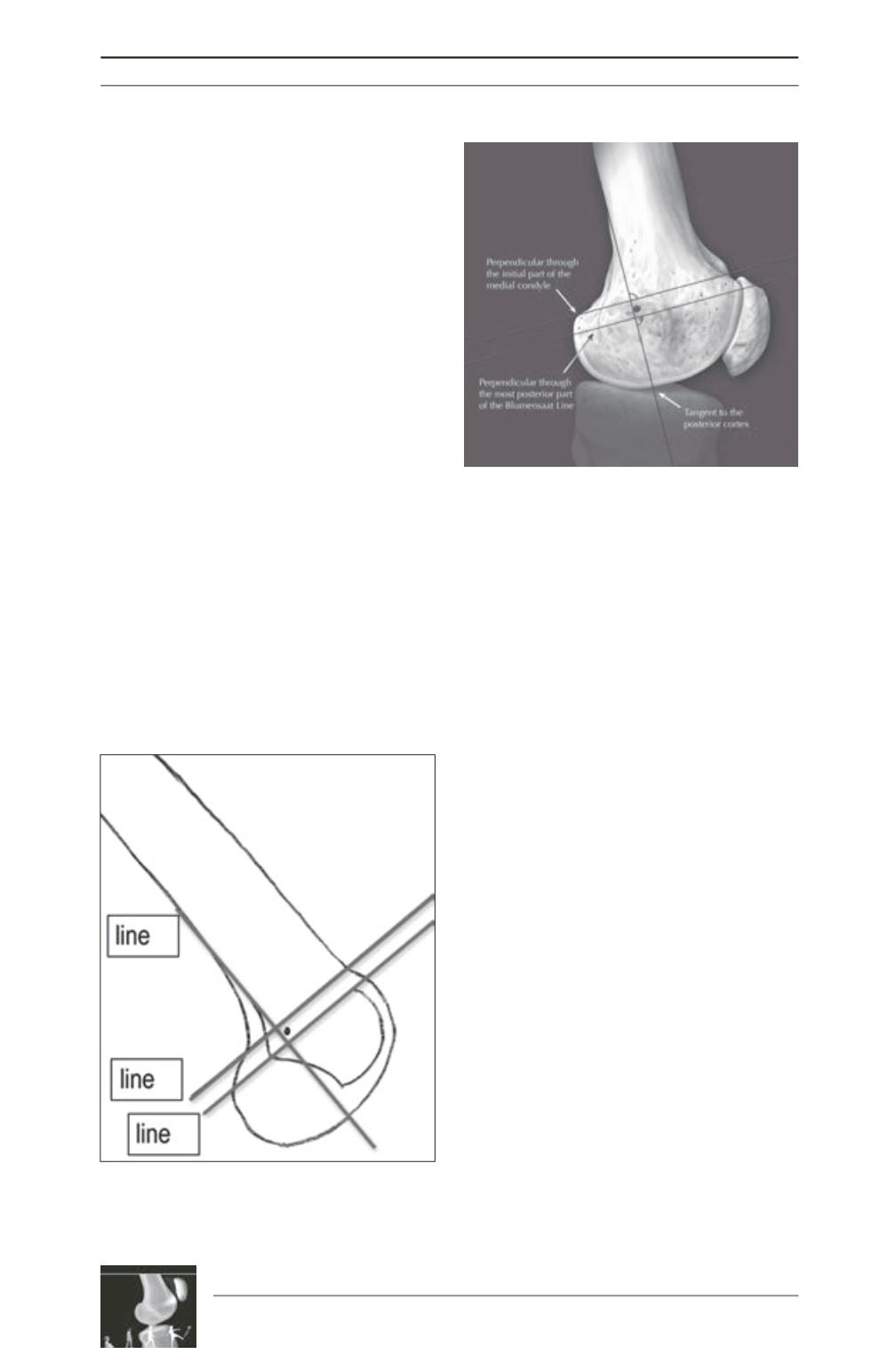
orientation: a first line in extension of the
posterior femoral cortex towards distal to
measure the anteroposterior position
(line 1)
, a
second line intersecting the contact of the
posterior femoral condyle with the posterior
cortex
(line 2)
, and a third line intersecting the
most posterior point of the Blumensaat line
(line 3)
, both perpendicular to line 1, measuring
the proximo-distal position (fig. 1 and 2) [14].
Anterior-posterior position:
The insertion
marker was located anterior to the posterior
cortical extension line in nearly all specimens,
with a mean location of 1.3 ± 1.7mm anterior to
line 1.
Proximal-distal position:
In all specimens the
marker ball was midway between line 2 and
line 3. The mean location was 2.5mm ± 0.8
distal to line 2. However, since all points were
within 5mm of each other, it was possible to
draw a 5mm diameter circle containing all
marker locations.
Although one can say that the mean position
we determined is not valid for every knee as the
distance of the single points is up to 5mm in the
proximal-distal direction, recent studies have
shown 15 that a distance of 5mm or less from
the anatomical femoral MPFL insertion is not
changing the MPFL isometry. Therefore, it is
recommended to use this radiographic landmark
intraoperatively due to the following benefits.
For intraoperative use, it is recommended to
first prepare the laminar patellar insertion and
to identify the anatomical MPFL layer, just in
between the joint capsula and the vastus
medialis obliquus muscle. A clamp is inserted
into this layer down to the femur, where the
tubercle and epicondyle is palpated. In this
area, a little skin incision of 3 millimeters is
performed and a guide wire is drilled into the
medial distal femur, in the area of the bony
landmarks, until it has a sechure fixation.
Afterwords, a cannulated drill (according to the
graft diameter with a minimum of 5mm) is
inserted over the guide wire down to the bone,
and the straight lateral view is taken with the
use of a fluoroscope. The drilled insertion point
is exactly there, where the cannulated drill
attaches to the bone. As described before, this
point should be anterior to the elongation of the
posterior cortex, distal to the origin of the
posterior medial condyle and proximal to the
most posterior point of the Blumesaat line
Fig. 1: Schematic drawing of a distal femur with the
reference lines, seen in a straight lateral view. The
circle is identifying the region, where an insertion
would be anatomical.
Fig. 2: Anatomical drawing with the same reference
lines to show the relation to the gross anatomy, i.e.
the medial epicondyle and the adductor tubercle.


