
M. Nelitz, H. Reichel, S. Lippacher
42
under fluoroscopic control. A guide pin is
placed at the femoral insertion. Fluoroscopy is
used to confirm the correct placement of the
guide-pin sparing the distal femoral physis.
Due to the concave curvature of the distal
femoral physis, the lateral radiograph alone
can be misleading for the determination of the
relation between the distal femoral physis and
the medial patellofemoral ligament [11, 18].
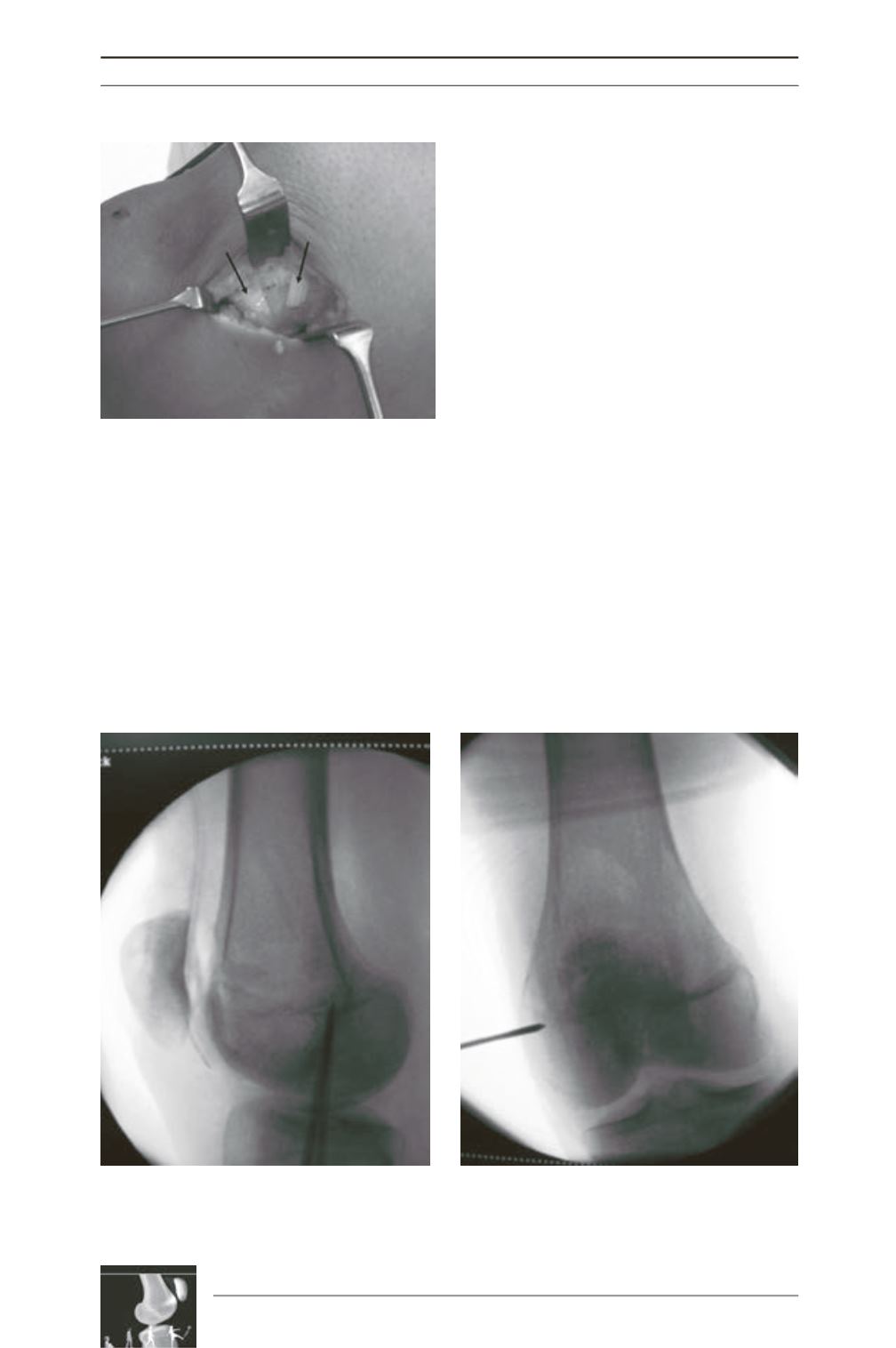
The cross-reference onto an AP view shows
that the same point that is projected on or
proximal to the physis on the lateral view is
distal to the physis on the AP view (fig. 2).
After meticulous verification of the entry-
point the guide-pin is drilled to the lateral
epicondyle distal to the physis (fig. 4). Then a
medial blind tunnel is drilled along the guide
pin to accommodate a double thickness of
graft to an adequate depth to allow optimal
graft tensioning.
The graft is then pulled between the second and
third layer to the femoral insertion point (fig. 3).
A locking suture is passed through the trans
epicondylar axis pulling the graft into the medial
tunnel. The knee is cycled several times from
full flexion to full extension with the graft under
tension. In this way, the graft is prestretched.
The graft is then secured within the medial
condyle tunnel using a bioresorbable interferen
ce screw with the knee flexed to 30° (fig. 5).
Fig. 1 : Double bundle insertion of the graft (arrows)
reconstructs the wide span of the patellar insertion
of the native MPFL.
Fig. 2 : Intraoperative cross-reference of the physis on the lateral view onto an ap view shows that the
same point that is projected on or proximal to the physis on the lateral view is distal to the physis on the
AP view.


