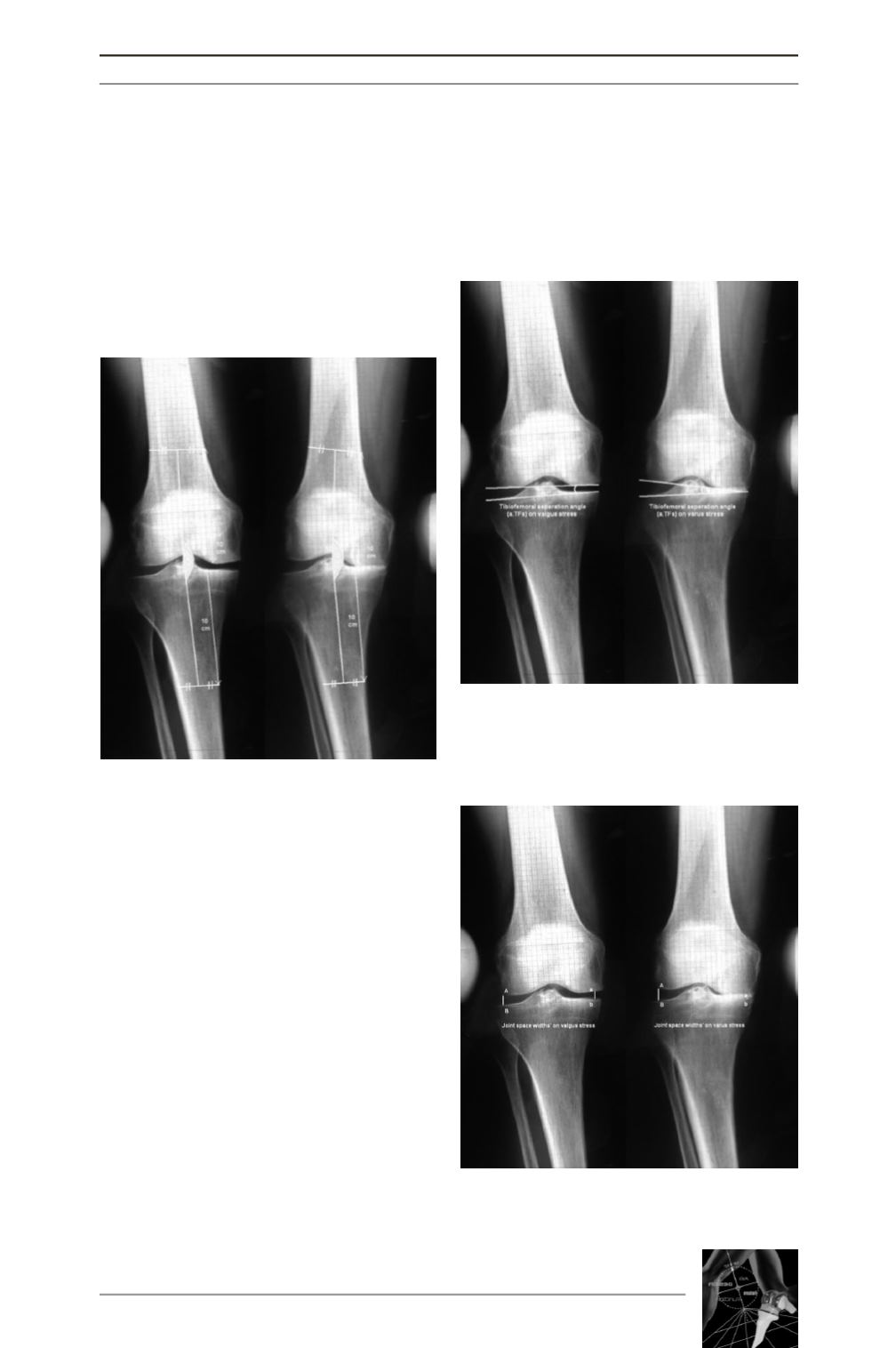

ting the femoral shaft 10 cm above the joint
line (fig. 2) and the second line was drawn
from the midpoint of the tibial spines to a
point bisecting the tibial shaft 10 cm below
the joint line [9, 12, 25]. Finally, these FTA
angles on the varus and valgus stress radio-
graphs were compared between the groups.
The femorotibial separation angle (TFS),
was the angle between the lines tangential to
the distal condyles and the tibial plateau arti-
cular surfaces (fig. 3). It was measured on
varus and valgus stress X-ray (measured
angles with open arms pointing to the medial
side of the knee result in negative values).
The medial and lateral compartment joint
space distances’ on the varus-valgus stress
radiographs were measured in millimeters
[26, 27]. Points that are described by Martin
[26] were chosen. Medial points (a,b) 5 mm
and lateral points (A,B) 10 mm from the
outer margins of the tibial plateau were
selected, and in each compartment the dis-
tance between the selected points was mea-
sured, respectively. The gaps between the
opposed subchondral plates of the compart-
ments on the varus-valgus stress were also
calculated as a ratio (fig. 4).
ARE STRESS X-RAYS USEFUL TO PLANMEDIAL SOFT TISSUE RELEASE PROCEDURES IN TOTAL KNEE ARTHROPLASTY?
13
Fig. 2 : Measurement protocol of the anatomi-
cal femorotibial angle on stress radiographs.
Fig. 3 : Measurement protocol of the tibiofe-
moral seperation angle on stress radiographs.
Fig. 4 : Measurement protocol of the com-
partment joint space widths’ on stress radio-
graphs.


