
S. Lustig, P. Neyret
44
and closely matches the size of the condyle to be
replaced as well as its position in the coronal,
sagittal, and rotational planes. Subsequent steps
are directed at determining gap and ligament
balance after virtual implant positioning,
removal of osteophytes, and stressing of the
ligaments and soft tissues. Osteophytes are
excised and a dynamic soft tissue balancing
algorithm is initiated. With an applied valgus
stress to tension the medial collateral ligament
(for medial UKA) or a varus stress to tension the
lateral structures (for lateral UKA), the three-
dimensional positions of the femur and the tibia
are captured throughout a passive range of knee
motion. A graphical representation of gap
spacing through the range of flexion is created
and determination is made regarding whether
the planned position of the femoral and tibial
component is adequate or adjustments can be
made to achieve the desired soft tissue balance.
By adjusting the implant position, including tibial
slope, depth of resection, and anteriorization or
distalization of the femoral component, the
virtual dynamic soft tissue balance can be
achieved. Adjustments in implant position and
size can be made to optimize soft tissue balance
and component tracking and position before
beginning bone preparation (fig. 2).
Unlike predicate robotic technologies that
provided haptic constraint through a robotic
arm, this system works with a combination of
speed and exposure control safeguards applied
through a lightweight, handheld, surgeondriven
semiautonomous robotic sculpting tool. In
“exposure” mode, the 5- or 6-mm burr is
continuously moving and is switched on and
off by the user by pressing or releasing a foot
pedal. A guard covers the burr, which only
extends past the guard when the burr is in the
“expected” cutting zone. The cutting zone is
predetermined by the surgeon during the
implant planning stage of the operation and the
system modulates the exposure distance of the
burr tip beyond the protective sheath. The
position data are continuously updated in real
time, resulting in fluid adjustments in the
position of the burr tip. When the handpiece is
moved out of the cutting zone, the burr retracts
within the guard. The second control mode is
“speed” mode in which the burr only becomes
active in the cutting zone. The speed of the
rotating burr is at full power/full speed until the
intended bone is removed or it is moved beyond
the desired preparation volume, at which point
it linearly ramps down to zero. After planning
for size, position, alignment, bone volume, and
gap balancing, the arthritic cartilage and bone
are methodically removed using the handheld
sculptor. The depth of bone to be removed is
color-coordinated, in which the target surface
is yellow, the green surface indicates 1mm of
bone still to be removed, the blue surface
indicates 2mm of bone still to be removed, and
the purple layer represents 3mm or more bone
to be removed (fig. 4).
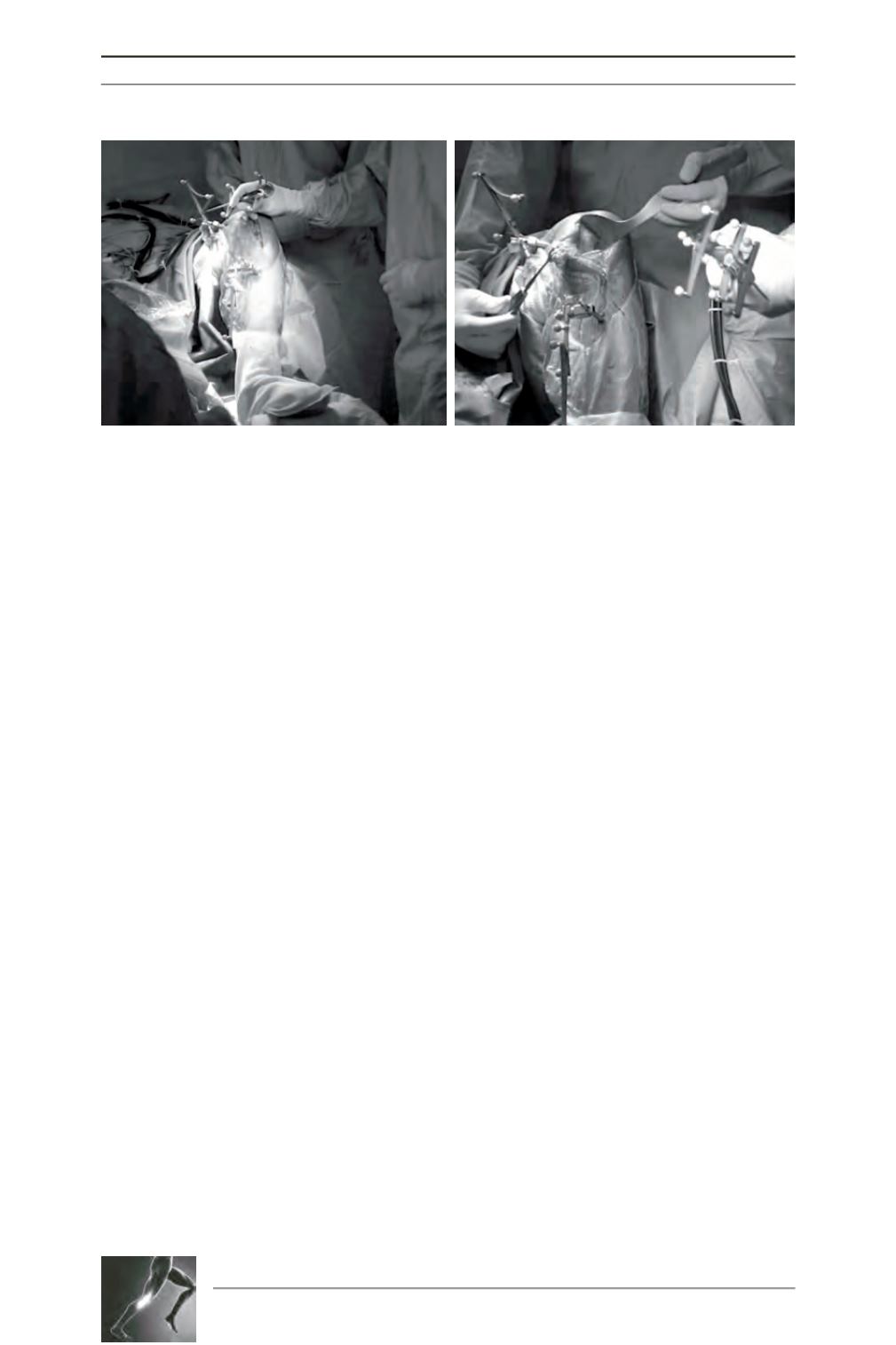
Fig. 2 : Surgical setting for a medial UKA.


