
Evidence of Trochlear Dysplasia in Patellofemoral Arthroplasty Designs
57
AP axes for the transverse plane. It is worth
noting that for most specimens, the frontal
resection plane is not parallel to the frontal
plane, but inclined anteriorly by a few
degrees.
The authors plotted the trochlear profiles of the
specimens at different flexion angles following
the same protocol published in a recent study
on TKA specimens [25]. Each specimen was
virtually rotated about its “origin” using Pro/
Engineer around the ML axis by the following
flexion angles: 0º, 15º, 30º and 45º. At each
flexion angle, the most anterior point on the
trochlea was marked, and the ML profile of the
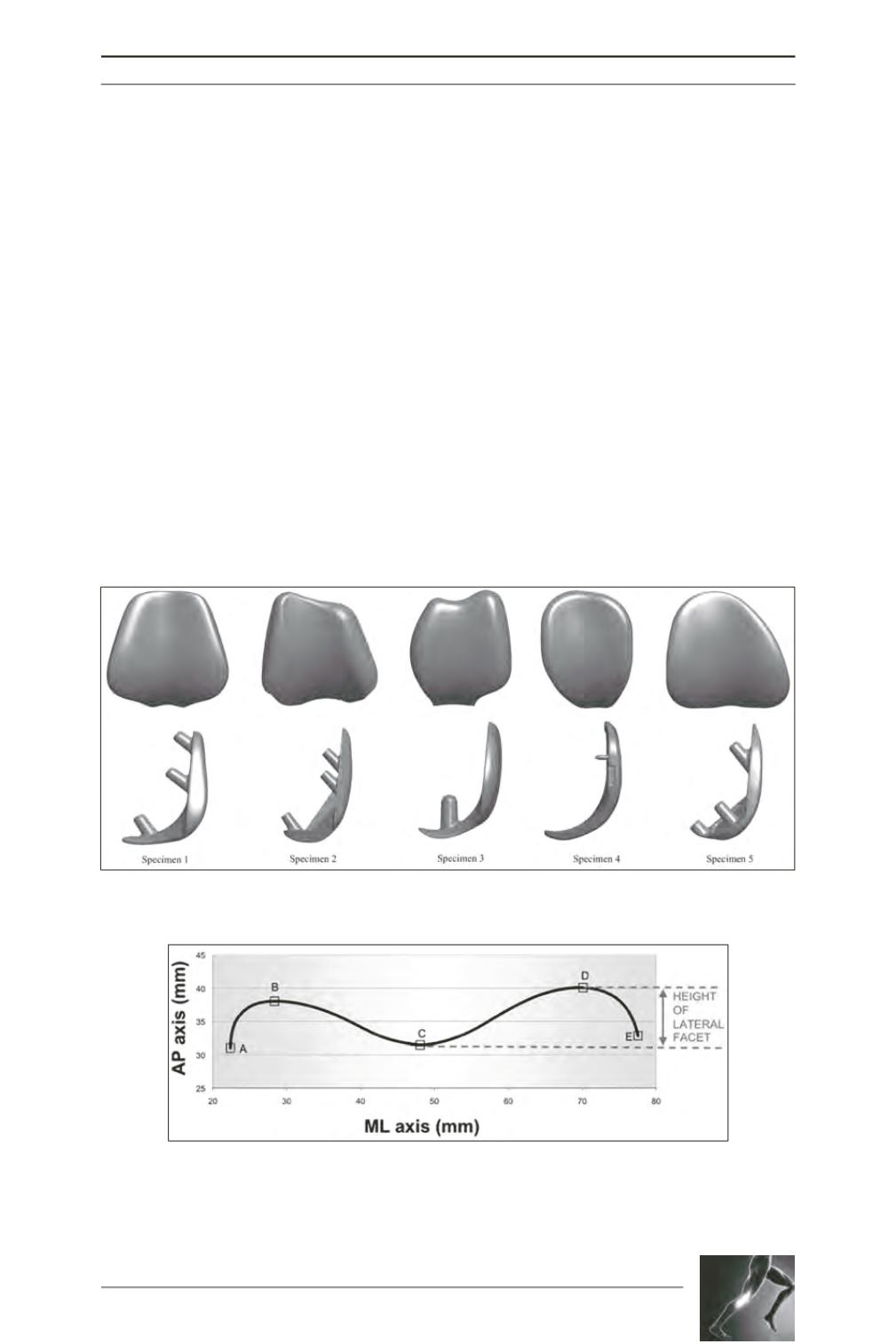
trochlea at that level was digitized (fig. 1).
All recorded coordinates were exported to
spreadsheets using M
icrosoft
® Excel
(Microsoft Corp, Redmond, WA). To enable
consistent geometric comparisons between all
specimens, the coordinates of right-sided
implants were mirrored to become super-
imposable with those of left-sided implants.
The two-dimensional ML profiles of each
prosthetic trochlea could therefore be
superposed and compared with its origin at the
intersection of (
i
) the midpoint between the
medial and lateral margin of each specimen
and (
ii
) the trochlear groove, or deepest point
on the sulcus, of each profile.
The “sulcus angle” of each profile was
calculated from the coordinates of the trochlear
groove and those of the highest points of the
medial and lateral facets (fig. 2). We used the
following criteria from the literature as
indicators of trochlear dysplasia: (
i
) sulcus
Fig. 1: Frontal and sagittal views of each specimen.
Fig. 2: Example of a two-dimensional trochlear profile at 30° of flexion. The letters
indicate points of inflexion of the trochlear profile: A medial extremity; B peak of
medial facet; C sulcus trough; D peak of lateral facet; E lateral extremity. The sulcus
angle is BCD, the height of the lateral facet is the z-coordinate difference between
points C and D.


