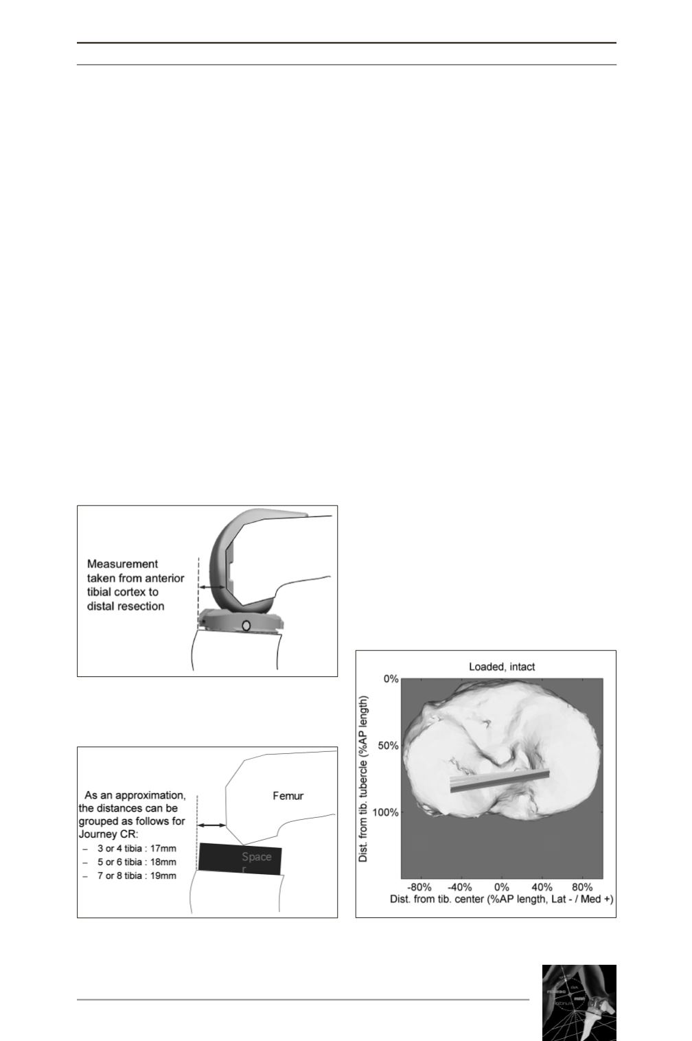

(fig. 1 a,b). After finishing the bonecuts of
tibia and femur the spacer was implanted in
flexion and positioned on the anterior edge of
the bony surface which simulates the anterior
edge of the chosen size of the tibial baseplate.
If the distance from distal femur to anterior
tibia edge is correct the contact point and pcl
balancing is correct. Of the 8 specimens
implanted the calculated step-off was correct
in 6 after finishing the bone cuts and in 2 spe-
cimens an additional tibia cut with 2-3 degrees
more slope was sufficient to achieve the cor-
rect step-off. No lift off of the tibial tray occur-
red during the tests.
The specimen was mounted on the knee kine-
matics rig described before and a loaded squat
with a constant vertical ankle force of 130 N
and constant medial and lateral hamstrings
forces of 50 N was performed between an esti-
mated 30° and 130° of knee flexion. The tra-
jectories of the reflective spherical markers on
tibia and femur were continuously recorded
using six infrared cameras (Vicon, Oxford,
UK) at 100 Hz. Kinematics were analysed and
the projected contact points of femur on tibia
were calculated. In two specimens with osteo-
porotic bone a femur fracture occurred during
the loaded squat, these were treated with
osteosynthesis. All PCL remained intact
during the tests.
RESULTS
Statistical calculations were not available at
the time of writing but comparing the patterns
of the kinematics of the native knee (fig. 2)
with the Journey CR knee implant (fig. 3) sho-
wed a considerable similarity in the weight-
bearing tests. The contact points on the medial
side of the Journey CR knee implant are at the
same position as the contact points of the nati-
ve knee. No paradoxical roll forward is seen in
the knee implants. All but one specimen had
contact points around the desired 60 % of the
ap diameter of the tibia plateau showing that
the PCL balancing apparently seems to work
quite well. The contact points on the lateral
side of the knee have a similar pattern in
flexion. The knee implant shows near exten-
sion a slightly more anterior contact point but
this is only marginal.
KINEMATICS OF AN ANATOMICLY-DESIGNED CRUCIATE RETAINING TOTAL KNEE ARTHROPLASTY…
193
Fig. 1a : Femur component
in sulcus insert
Fig. 1b : Spacer in situ and
calculated step off distances
Fig. 2 : Loaded contact
points native knee


